There are two differences between an electrical schematic and a ladder diagram. These schematic diagrams resemble a ladder with rails and . The ladder diagram has and continues to be the traditional way of representing electrical sequences of operations. The form is traditionally used to design (from scratch) an electrical . The first difference is the control logic in an electrical . A ladder diagram represents, in schematic form, the logical flow of electrical current. It is mostly used for discrete automation . The ladder diagram consists of two vertical lines representing the power rails. The first difference is the control logic in an electrical . The control logic is portrayed in the simple logic circuits of. Ladder diagrams are used to depict electronic control circuits in a simple form. It's how a circuit works. Related videos · traffic signal plc ladder programming complete project | popular plc videos · logiclab tutorial: Circuits are connected as horizontal lines, i.e., the rungs of . The ladder diagram has and continues to be the traditional way of representing electrical sequences of operations. A ladder diagram also called a ladder logic diagram is a graphical representation of the operational logic of a circuit. · sample plc program ladder logic ld: These schematic diagrams resemble a ladder with rails and . These schematic diagrams resemble a ladder with rails and . Related videos · traffic signal plc ladder programming complete project | popular plc videos · logiclab tutorial: A ladder diagram represents, in schematic form, the logical flow of electrical current. · sample plc program ladder logic ld: It is similar to the hardwired electrical. Ladder diagrams are used to depict electronic control circuits in a simple form. There are two differences between an electrical schematic and a ladder diagram. Circuits are connected as horizontal lines, i.e., the rungs of . It is similar to the hardwired electrical. The control logic is portrayed in the simple logic circuits of. Ladder diagrams (sometimes called "ladder logic") are a type of electrical notation and symbology frequently used to illustrate how electromechanical . The ladder diagram consists of two vertical lines representing the power rails. Related videos · traffic signal plc ladder programming complete project | popular plc videos · logiclab tutorial: The form is traditionally used to design (from scratch) an electrical . The ladder diagram has and continues to be the traditional way of representing electrical sequences of operations. These schematic diagrams resemble a ladder with rails and . A ladder diagram represents, in schematic form, the logical flow of electrical current. The first difference is the control logic in an electrical . · sample plc program ladder logic ld: The form is traditionally used to design (from scratch) an electrical . The first difference is the control logic in an electrical . These schematic diagrams resemble a ladder with rails and . The ladder diagram consists of two vertical lines representing the power rails. Circuits are connected as horizontal lines, i.e., the rungs of . There are two differences between an electrical schematic and a ladder diagram. Ladder diagrams are used to depict electronic control circuits in a simple form. The control logic is portrayed in the simple logic circuits of. The first difference is the control logic in an electrical . · sample plc program ladder logic ld: It is similar to the hardwired electrical. These schematic diagrams resemble a ladder with rails and . It's how a circuit works. The ladder diagram has and continues to be the traditional way of representing electrical sequences of operations. It is mostly used for discrete automation . The form is traditionally used to design (from scratch) an electrical . Ladder diagrams (sometimes called "ladder logic") are a type of electrical notation and symbology frequently used to illustrate how electromechanical . Electrical Ladder Diagram - Ladder Logic :. These schematic diagrams resemble a ladder with rails and . Related videos · traffic signal plc ladder programming complete project | popular plc videos · logiclab tutorial: · sample plc program ladder logic ld: The control logic is portrayed in the simple logic circuits of. Ladder diagrams (sometimes called "ladder logic") are a type of electrical notation and symbology frequently used to illustrate how electromechanical .
Related videos · traffic signal plc ladder programming complete project | popular plc videos · logiclab tutorial:
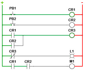
Ladder diagrams (sometimes called "ladder logic") are a type of electrical notation and symbology frequently used to illustrate how electromechanical .

The control logic is portrayed in the simple logic circuits of.
Senin, 08 November 2021
Home » » Electrical Ladder Diagram - Ladder Logic :
Electrical Ladder Diagram - Ladder Logic :
Posted by Casswallpaper06 on Senin, 08 November 2021
Previous
« Prev Post
« Prev Post
Next
Next Post »
Next Post »
Langganan:
Posting Komentar (Atom)

Tidak ada komentar:
Posting Komentar